Difference between revisions of "Hawkins Class Cruiser (1917)"
m (→Machinery) |
|||
| Line 2: | Line 2: | ||
==Machinery== | ==Machinery== | ||
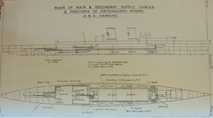
| − | [[File:ARTS1916Plate48.jpg|thumb|300px|'''Electrical Distribution Scheme''<ref>''Annual Report of the Torpedo School, 1916'', Plate 48.</ref>]] | + | [[File:ARTS1916Plate48.jpg|thumb|300px|'''Electrical Distribution Scheme'''<ref>''Annual Report of the Torpedo School, 1916'', Plate 48.</ref>]] |
===Boilers=== | ===Boilers=== | ||
===Engines=== | ===Engines=== | ||
Revision as of 12:25, 19 January 2012
Four of the five cruisers of the Hawkins Class (sometimes called the Raleigh Class or Effingham Class) that were ordered were completed as cruisers, but one was completed as the aircraft carrier Vindictive. Although their 7.5-in guns lent them to the notion of being heavy cruisers, their single pedestal mountings yet resembled the British model of an early light cruiser.
Contents
Machinery

Boilers
Engines
Generators
In 1916, it was approved that the ships were to be given four 105-kw dynamos at 220 volts.[2]
Armament
Guns
The guns had armoured shields of 1 inch thickness on the face, sides and top, weighing 7.25 tons.[3]
Torpedoes
- Two 21-in submerged broadside tubes forward, angled 90 degrees and horizontal.[4]
- Four 21-in above-water tubes, fixed and with gyro angle pads for adjusting torpedoes.[5]
Fire Control
Rangefinders
Evershed Bearing Indicators
The ships almost surely had Evershed gear for gun control from delivery, as approval for their outfits was issued in 1916.[6]
Gunnery Control
Control Positions
Control Groups
Directors
Transmitting Stations
Dreyer Table
Fire Control Instruments
Torpedo Control
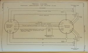
The torpedoes could be controlled and fired from the CT or the TCT, with firing keys routed through COSes in the TS.
The CT had
- Two gyro angle transmitters
- Two order transmitters
- One range receiver (from TCT)
- One range and torpedo deflection transmitter (to TCT)
- One bearing transmitter (to TCT)
The TCT had
- Two gyro angle transmitters
- Two order transmitters
- One range transmitter (to CT)
- One range and torpedo deflection receiver (from CT)
- One bearing transmitter (from CT)
The tubes had:
- Two gyro angle receivers, one from CT and one from TCT
- Two order receivers, one from CT and one from TCT
All three locations had fixed Navyphone connections to the other two, and the CT also had voice pipes to the torpedo tubes.
See Also
Footnotes
- ↑ Annual Report of the Torpedo School, 1916, Plate 48.
- ↑ Annual Report of the Torpedo School', 1916', p. 120.
- ↑ Technical History and Index, Vol 3, Part 28, p. 18.
- ↑ Annual Report of the Torpedo School, 1916, p. 35.
- ↑ Annual Report of the Torpedo School, 1916, p. 35.
- ↑ Annual Report of the Torpedo School', 1916', p. 175.
- ↑ Annual Report of the Torpedo School, 1916, Plate 85.
- ↑ Annual Report of the Torpedo School, 1916, p. 151.
Bibliography
