Torpedo Director: Difference between revisions
No edit summary |
No edit summary |
||
| Line 24: | Line 24: | ||
===1905=== | ===1905=== | ||
The two directors described in service are a semi-circular one for trainable tubes, presumably Pattern 1192, and a 60 degree one for fixed tubes and dropping gear, presumably 1193. A double foresight was available when used with double VII. B tubes. A further variant was available with a tangent bar for use in 4-in CT openings of "later ships".<ref>''Torpedo Drill Book, 1905'', p. 376</ref> | The two directors described in service are a semi-circular one for trainable tubes, presumably Pattern 1192, and a 60 degree one for fixed tubes and dropping gear, presumably 1193. A double foresight was available when used with double VII. B tubes. A further variant was available with a tangent bar for use in 4-in CT openings of "later ships".<ref>''Torpedo Drill Book, 1905'', p. 376</ref> | ||
===1909=== | |||
ART1909 p. 22. | |||
The introduction of heater torpedoes with speeds above the 40 knot maximum on the radius bars of the directors in service necessitated that their scales be regraduated by 2/3rds. This gave a max torpedo speed of 60 knots . | |||
The directors as they stand at present was; | |||
* 1895 w/ modified rear- and fore-sights but no other alteration were supplied to torpedo craft not supplied with heaters, for their tubes only and for ships with dropping gear. | |||
* 1895 as above, but with re-graduated scales were supplied to torpedo craft with heaters for use at their tubes | |||
p. 23 | |||
* Patterns 1192, 1193 and 1895 directors with tangent bars and regraduated scales supplied to TBDs equipped for fore bridge firing for use at their fore bridge | |||
* 1895, 2006 and 2391/2392 for "ships" (from the context, this appears to mean ships larger than destroyers) will not be regraduated, as their heaters will be fired at slow-speed settings at long ranges. | |||
If it were necessary to run a fast heater from a director not regraduated, speed of torpedo and enemy were to be halved on the sights (G&T orders Feb 1st 1909) | |||
A ''Harrier'' (gunboat HMS Harrier?) is mentioned as having double tubes demanding a double foresight -- she was not to receive night sights based on the obsolete nature of her tubes. | |||
===1910=== | ===1910=== | ||
| Line 59: | Line 75: | ||
===Pattern 1192/1192a=== | ===Pattern 1192/1192a=== | ||
A large, semicircular director, presumably of the director triangle principle, not used in any modern ships as of 1912<ref>''Torpedo Drill Book, 1912'', p. 494.</ref>. If a 1192a existed, it was similar, but made stronger in its pivots and sighting bar.<ref>''Torpedo Drill Book, 1914'', p. 564.</ref> | A large, semicircular director, presumably of the director triangle principle, not used in any modern ships as of 1912<ref>''Torpedo Drill Book, 1912'', p. 494.</ref>. If a 1192a existed, it was similar, but made stronger in its pivots and sighting bar.<ref>''Torpedo Drill Book, 1914'', p. 564.</ref> In 1909, | ||
===Pattern 1193/1193a=== | ===Pattern 1193/1193a=== | ||
| Line 78: | Line 94: | ||
===Pattern 2390=== | ===Pattern 2390=== | ||
[[File:ARTS1914Plate11.jpg|thumb|400px| | [[File:ARTS1914Plate11.jpg|thumb|400px| Disc added to 2390 to help set course of enemy as expressed as inclination.<ref>''The Annual Report of the Torpedo School, 1914'', Plate 11.</ref>]] | ||
Available by 1912 at least, supplied to torpedo craft with heater torpedoes. Similar to Pattern 1895, but graduated for higher torpedo speeds.<ref>''Torpedo Drill Book, 1912'', p. 494.</ref><ref>''Torpedo Drill Book, 1914'', p. 564.</ref> | Available by 1912 at least, supplied to torpedo craft with heater torpedoes. Similar to Pattern 1895, but graduated for higher torpedo speeds.<ref>''Torpedo Drill Book, 1912'', p. 494.</ref><ref>''Torpedo Drill Book, 1914'', p. 564.</ref> | ||
| Line 88: | Line 104: | ||
===Pattern 2391/2391a=== | ===Pattern 2391/2391a=== | ||
[[File:ARTS1909Plate7.jpg|thumb|400px]] | [[File:ARTS1909Plate7.jpg|thumb|400px| the scale depicted is graduated for a Mark VI* heater torpedo (35 knots to 4,000 yards)<ref>''The Annual Report of the Torpedo School, 1909'', p. 23.</ref>]] | ||
[[File:ARTS1910Plate9.jpg|thumb|400px]] | [[File:ARTS1910Plate9.jpg|thumb|400px| Additional maximum firing range scales for use on Pattern 2391/2391a,2392/2392a directors using different tupes of torpedoes.]] | ||
A "right handed" director for use in conning and director towers of ships from at least 1909-1910. They had open sights as well as the capability to mount a telescope.<ref>''The Annual Report of the Torpedo School, 1910'', p. 32.</ref><ref>''The Annual Report of the Torpedo School, 1909'', Plate 7.</ref> The 2391a was fitted for gyro angling.<ref>''Torpedo Drill Book, 1914'', p. 564.</ref> | A "right handed" director for use in conning and director towers of ships from at least 1909-1910. They had open sights as well as the capability to mount a telescope.<ref>''The Annual Report of the Torpedo School, 1910'', p. 32.</ref><ref>''The Annual Report of the Torpedo School, 1909'', Plate 7.</ref> The 2391a was fitted for gyro angling.<ref>''Torpedo Drill Book, 1914'', p. 564.</ref> | ||
The telescopes used initially had crosswires, a 5-power magnification, and field of view of 7 degs, 10 minutes. It was not given illumination, as the regular sights would be used at night. Improvements in moving the rear sight along the tangent bar were incorporated, and an additional scale along the sighting bar allowed the maximum firing range to be read off directly. A disc labelled 0 to 180 degrees, port and starboard was added and a pointer on the speed and course of enemy bar. This disc was fitted only when a director was mounted on its ship, as the disc was oriented to own ship's keel, with 0 degrees being forward. The intent was that enemy heading could be communicated and set on the sight as a relative heading to own ship's course.<ref>''The Annual Report of the Torpedo School, 1909'', p. 23.</ref> | |||
===Pattern 2392/2392a=== | ===Pattern 2392/2392a=== | ||
[[File:ARTS1909Plate7.jpg|thumb|400px| A Pattern 2391 director similar to the 2392. The 2392 would differ by having its telescope mounted to the left of the sighting bar. The scale depicted is graduated for a Mark VI* heater torpedo (35 knots to 4,000 yards)<ref>''The Annual Report of the Torpedo School, 1909'', p. 23.</ref>]] | |||
A "left handed" director for use in conning and director towers of ships from at least 1909-1910. They had open sights as well as the capability to mount a telescope, but on the left side of the sighting bar.<ref>''The Annual Report of the Torpedo School, 1910'', p. 32.</ref><ref>''The Annual Report of the Torpedo School, 1909'', Plate 7.</ref> The 2392a was fitted for gyro angling.<ref>''Torpedo Drill Book, 1914'', p. 564.</ref> | A "left handed" director for use in conning and director towers of ships from at least 1909-1910. They had open sights as well as the capability to mount a telescope, but on the left side of the sighting bar.<ref>''The Annual Report of the Torpedo School, 1910'', p. 32.</ref><ref>''The Annual Report of the Torpedo School, 1909'', Plate 7.</ref> The 2392a was fitted for gyro angling.<ref>''Torpedo Drill Book, 1914'', p. 564.</ref> | ||
Revision as of 16:40, 27 February 2011
A Torpedo Director is merely a sight for torpedo fire, more similar to a settable gunsight than to a gunnery director.
Director Triangle
The Royal Navy began the 20th century with a series of sights that characterized the torpedo firing problem according to the Director Triangle formed by the path of the torpedo, the line of sight at the moment of firing to the target, and the path of the target between firing and impact. It delivered a number of sights which embodied this geometry, including the Pattern 2006 Torpedo Director.
Deflection Triangle
In 1915[1], the Royal Navy started to migrate toward a different geometric model called the Deflection Triangle, formed by the path of the torpedo, the line of sight, and the speed-across of the target.[Fact Check]
Tangent Bars
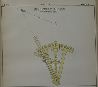
Basic torpedo directors were constructed such that they only worked precisely when mounted on or very near the torpedo tube they aimed. In some circumstances, it was desirable or necessary to have the sight function remotely from the torpedo tube by a considerable distance. In this case, a small additional arm called a "Tangent Bar" would be affixed to a director to offset the rear sighting arch a suitable distance so that the torpedo would converge on the target at the proper range. A consequence of adding this to the problem was that the range to the target had to be known (at least approximately... inaccuracy in ranging would just reduce the value of the correction).
Progress
1903
1904
plates Discussion of "existing Dumaresqs marks I and II" for consideration with new dial plates, and creation of range clock drums graduated in yards/minute. description of range corrector (pamphlet G 4023/08, pp 45-45) cross-connection of range transmitters being trialled in Dreadnought, King Ed VII, Exmouth, Prince of Wales, Shannon, Indomitable.
1905
The two directors described in service are a semi-circular one for trainable tubes, presumably Pattern 1192, and a 60 degree one for fixed tubes and dropping gear, presumably 1193. A double foresight was available when used with double VII. B tubes. A further variant was available with a tangent bar for use in 4-in CT openings of "later ships".[2]
1909
ART1909 p. 22. The introduction of heater torpedoes with speeds above the 40 knot maximum on the radius bars of the directors in service necessitated that their scales be regraduated by 2/3rds. This gave a max torpedo speed of 60 knots .
The directors as they stand at present was;
- 1895 w/ modified rear- and fore-sights but no other alteration were supplied to torpedo craft not supplied with heaters, for their tubes only and for ships with dropping gear.
- 1895 as above, but with re-graduated scales were supplied to torpedo craft with heaters for use at their tubes
p. 23
- Patterns 1192, 1193 and 1895 directors with tangent bars and regraduated scales supplied to TBDs equipped for fore bridge firing for use at their fore bridge
- 1895, 2006 and 2391/2392 for "ships" (from the context, this appears to mean ships larger than destroyers) will not be regraduated, as their heaters will be fired at slow-speed settings at long ranges.
If it were necessary to run a fast heater from a director not regraduated, speed of torpedo and enemy were to be halved on the sights (G&T orders Feb 1st 1909)
A Harrier (gunboat HMS Harrier?) is mentioned as having double tubes demanding a double foresight -- she was not to receive night sights based on the obsolete nature of her tubes.
1910
Lt Col Chaytor's Torpedo Danger Area Instrument (Plate 10 and text)see also ARTS1909 p22
1911
1914
p. 32 and plates 12-16 Walker's Instrument
1915
In 1915, trials were carried out to compare the "wire" and "theodolite" methods of aligning directors for submerged tubes, but results were not yet complete. Until they were available, contract-built ships were to have their directors aligned by theodolite means. Extensive description of the method is outlined in The Annual Report of the Torpedo School, 1915.[3]
A new design of director for capital ships was being undertaken. It would not have a tangent bar, and would therefore offer a stronger design. Additionally, there was talk of using periscopes to keep personnel clear of gun blast. This blast was studied in Iron Duke when directors were placed in secondary hoods, and found to be so considerable that directors were to be placed in conning and torpedo control towers only, and no further hoods would be built. The tubes were to be dirigible from either position, with communications and firing circuits laid to both towers.
A director called Hallet's Director was tried, apparently unsuccessfully, as it was returned for disposal. Seven examples of Lambert's Attack Director were under trial at sea. Note was made of directors having been reassembled incorrectly after maintenance, resulting in poorly aimed torpedoes.[4] One gotcha that was to be corrected was to ensure that sliders would be modified so they could not be reversed upon reassembly. [5]
Hinged stands for directors were tried in Invincible and Hercules, but found not to be worth the expense or the possibility of errors in alignment. Henceforth, they would only be fitted where absolutely necessary. [6]
Directors would henceforth be illuminated for use at night. An aperture with variable stop and violet glass would use a switch to turn on and off.[7][8]
The director telescope Pattern 2393's 6-power magnification was criticised at sea as being too high, rendering it difficult to see in haze and rain. Six telescopes answering to a 3-power specification had been ordered for trial.[9]
A promising wander mark telescope from the German Goertz company had been ordered before the war, but not taken before the war started. It was seen as having some promise as a director telescope or for use on the Middleton Plotter in lieu of electrical contacts.
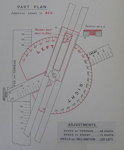
An enterprising torpedoman aboard Blonde had added a 4-inch diameter brass disc plate to the enemy speed slider on his Torpedo Director Pattern 2390 to permit the enemy's heading to be expressed or read as an inclination to line of sight. This would especially help the adjustment of a director at a trainable tube, but no explicit recommendation was spelled out despite a supportive description of its utility.
It was concluded from practical experience that the deflection triangle was superior to the director triangle as a means of setting the director.
Pattern 1192/1192a
A large, semicircular director, presumably of the director triangle principle, not used in any modern ships as of 1912[10]. If a 1192a existed, it was similar, but made stronger in its pivots and sighting bar.[11] In 1909,
Pattern 1193/1193a
Had a 60 degree arc, used in early torpedo craft. If a 1193a existed, it was similar, but made stronger in its pivots and sighting bar.[12]
Pattern 1895/1895a
Very similar to the 1193, the 1895 had a 60 degree arc and was used in early torpedo craft. If a 1895a existed, it was similar, but made stronger in its pivots and sighting bar.[13]
Pattern 2006/2006a
Introduced about 1905[14], used in conning towers and director towers of "earlier ships" (as judged by 1912[15]) with a tangent bar, and perhaps also at times directly on tubes[Citation needed]. The 2006a was fitted for adapting to gyro angles.[16]
Pattern 2380
Similar to the Pattern 2390a, but larger and of improved construction.[17]
Pattern 2389
Available by 1910 at least.[18] Same as the Pattern 2390, but fitted for use from the bridge, presumably by the addition of a tangent bar.[19]
Pattern 2390

Available by 1912 at least, supplied to torpedo craft with heater torpedoes. Similar to Pattern 1895, but graduated for higher torpedo speeds.[21][22]
Pattern 2387
Available from 1910 at least.[23] Same as Pattern 1192, but fitted for use from the bridge by addition of a tangent bar.[24]
Pattern 2388
Available by 1910 at least.[25] Same as Pattern 1193, but fitted for use from the bridge by addition of a tangent bar.[26]
Pattern 2391/2391a

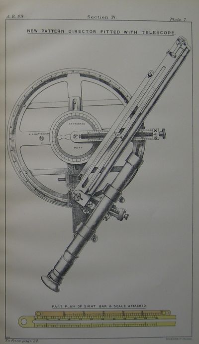
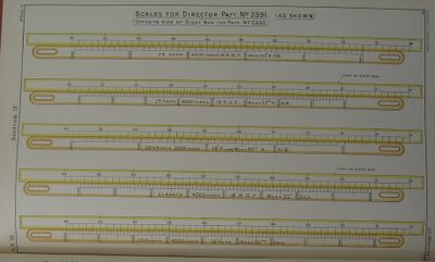
A "right handed" director for use in conning and director towers of ships from at least 1909-1910. They had open sights as well as the capability to mount a telescope.[28][29] The 2391a was fitted for gyro angling.[30]
The telescopes used initially had crosswires, a 5-power magnification, and field of view of 7 degs, 10 minutes. It was not given illumination, as the regular sights would be used at night. Improvements in moving the rear sight along the tangent bar were incorporated, and an additional scale along the sighting bar allowed the maximum firing range to be read off directly. A disc labelled 0 to 180 degrees, port and starboard was added and a pointer on the speed and course of enemy bar. This disc was fitted only when a director was mounted on its ship, as the disc was oriented to own ship's keel, with 0 degrees being forward. The intent was that enemy heading could be communicated and set on the sight as a relative heading to own ship's course.[31]
Pattern 2392/2392a

A "left handed" director for use in conning and director towers of ships from at least 1909-1910. They had open sights as well as the capability to mount a telescope, but on the left side of the sighting bar.[33][34] The 2392a was fitted for gyro angling.[35]
See Also
Footnotes
- ↑ The Annual Report of the Torpedo School, 1915, pp. 31-32.
- ↑ Torpedo Drill Book, 1905, p. 376
- ↑ The Annual Report of the Torpedo School, 1915, pp. 28-30.
- ↑ Torpedo Order No. 39 of May 1st, 1914, (G. 14148/14).
- ↑ (A.L. 1/4/14. G. 13173/14)
- ↑ (G. 01191/13)
- ↑ (G. 8725/13)
- ↑ The Annual Report of the Torpedo School, 1915, pp. 30.
- ↑ (G. 13028/14)
- ↑ Torpedo Drill Book, 1912, p. 494.
- ↑ Torpedo Drill Book, 1914, p. 564.
- ↑ Torpedo Drill Book, 1914, p. 564.
- ↑ Torpedo Drill Book, 1914, p. 564.
- ↑ Torpedo Drill Book, 1905, p. 381.
- ↑ Torpedo Drill Book, 1912, p. 495.
- ↑ Torpedo Drill Book, 1914, p. 564.
- ↑ Torpedo Drill Book, 1914, p. 564.
- ↑ The Annual Report of the Torpedo School, 1910, p. 32.
- ↑ Torpedo Drill Book, 1914, p. 564.
- ↑ The Annual Report of the Torpedo School, 1914, Plate 11.
- ↑ Torpedo Drill Book, 1912, p. 494.
- ↑ Torpedo Drill Book, 1914, p. 564.
- ↑ The Annual Report of the Torpedo School, 1910, p. 32.
- ↑ Torpedo Drill Book, 1914, p. 564.
- ↑ The Annual Report of the Torpedo School, 1910, p. 32.
- ↑ Torpedo Drill Book, 1914, p. 564.
- ↑ The Annual Report of the Torpedo School, 1909, p. 23.
- ↑ The Annual Report of the Torpedo School, 1910, p. 32.
- ↑ The Annual Report of the Torpedo School, 1909, Plate 7.
- ↑ Torpedo Drill Book, 1914, p. 564.
- ↑ The Annual Report of the Torpedo School, 1909, p. 23.
- ↑ The Annual Report of the Torpedo School, 1909, p. 23.
- ↑ The Annual Report of the Torpedo School, 1910, p. 32.
- ↑ The Annual Report of the Torpedo School, 1909, Plate 7.
- ↑ Torpedo Drill Book, 1914, p. 564.
Bibliography

