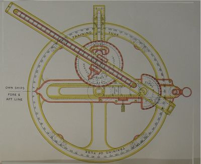
Line of Sight Director

The Line of Sight Director (sometimes "Torpedo Line of Sight Indicator") was designed around 1915, to be located on a fixed stand on the fore bridge of a destroyer or a light cruiser.[2]
Design
The circular device was fixed on a stand and in many ways resembled the Torpedo Director Pattern 2006, except that the torpedo arm (graduated up to 48 knots) could rotate about the fixed outer ring to any angle of torpedo tube training from 0 to 180 degrees green or red and be clamped into position.
The enemy bar was graduated to 40 knots and the sight arm carried a possible shot strip for the torpedo and setting in use. A Robinson Disc permitted enemy inclination to be read clearly, and an half-disc allowed director angle to be read off, 0 to 90 degrees either side of the torpedo arm.[3]
Adaptation

| Legend for Deflection Sighting Modifications | |
|---|---|
| A | Circular ring fitted to torpedo arm |
| B | Deflection ring, locks to A |
| C | Spring locking pin to engage B |
| D | Sight arm and 2 sights |
| E | Deflection pointer |
| F | Spring washer nut |
| G | Deflection limit stops |
| H | Torpedo arm |
| J | Torpedo training pointer |
By mid 1917, in conformance with the Royal Navy's change to deflection sighting, these devices were considerably simplified to work by deflection.
The enemy bar, the existing sight bar and both discs were removed. The torpedo bar and its rotation clamp remained in place. A circular ring (A) rode on the torpedo arms and carried the rest of the mechanism. A deflection ring (B) rode within the circular ring A and could be locked in any of three positions by a spring catch (C), such that a deflection scale suitable for the torpedo speed in use could be read directly from a pointer (E) on the new sight arm (D) in knots deflection, left or right. Limit arcs (G in image to right) could limit the deviation of sight arm from torpedo arm for use at night.
The user would verify that he had the correct portion of the deflection scale showing and that the deflection ring (B) was locked into place by the spring catch. The sight arm would be rotated against friction washer (F) to the desired deflection. The torpedo arm (H) would then be rotated until torpedo pointer (J) matched the tube training angle or the departure angle of the tube and the gyro angle in use. [5]
See Also
Footnotes
Bibliography