Torpedo Director Pattern 2391

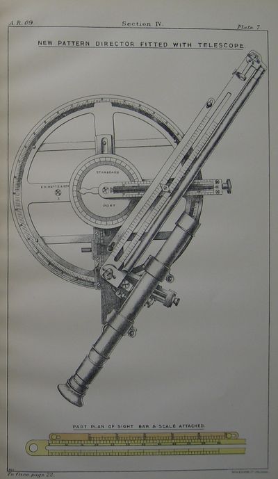
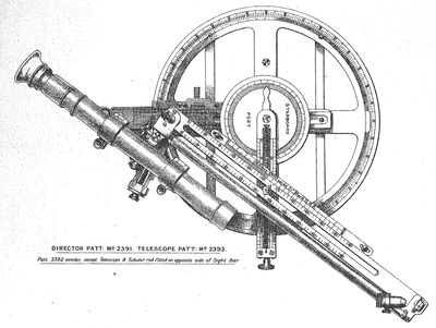
The Torpedo Director Pattern 2391 (along with the 2391a, 2392 and 2392a) was a circular British torpedo director used in conning and torpedo control towers of surface ships, introduced by at least 1909-1910.[3]
Design
The 2391 was a "right handed" director for installation, and the 2392 a "left handed" model. The "handedness" of the design was due to the fact that they were fitted with tangent bars that had to point to the mouth of the tube being fired, and this might be to left or right. They had open sights as well as the capability to mount a telescope.[4][5] The 2391a and 2392a were adaptations fitted for gyro angling, sometime after 1912.[6][7]
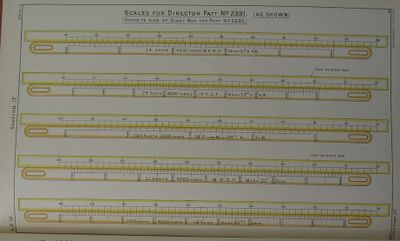
They featured a possible shot scale alongside the sight bar which was graduated according to the torpedo in use and obviated the need for performing arithmetic as was required by the sight arm scaling used in the Pattern 2006.
In 1912, a design was approved to add a Carpenter's disc(what is this?) sight to the director.[8]
The telescopes used initially had crosswires, a 5-power magnification, and field of view of 7 degs, 10 minutes. It was not given illumination, as the regular sights would be used at night. Improvements in moving the rear sight along the tangent bar were incorporated, and an additional scale along the sighting bar allowed the maximum firing range to be read off directly. A disc labelled 0 to 180 degrees, port and starboard was added and a pointer on the speed and course of enemy bar. This disc was fitted only when a director was mounted on its ship, as the disc was oriented to own ship's keel, with 0 degrees being forward. The intent was that enemy heading could be communicated and set on the sight as a relative heading to own ship's course.[9]
Alterations

In this form, it may have been called a T.D.S. Mark III.
The original telescope in use was a Pattern 2393 of 5 power and field 7 degrees 10 minutes, but in 1915, the need for the lower power scope for haze and rain was realised. A quick trial resulted in the Pattern 3341 of 2.5 power, ~25 degree field and 2.5 pounds being introduced, likely in 1915 or 1916.[11][12] The 3341 was later replaced by a lighter Ottway design weighing just 1.5 pounds first tested in 1916.[13]
Around 1910, as on the 2006, the directors were provided slides underneath permitting 3 inches of lateral motion to look around obstacles.[14]
The -A (or -a, variously) variants were created to be able to adapt to gyro angles, seemingly during 1912 and 1913. Inquiries were issued as to the state of these conversions in late 1913.[15]
In April 1914, the Admiralty ordered eight Pattern 2391s and eight 2392s to be exchanged for -A models, two of each stripe in Britannia, Indomitable and Inflexible, and one of each stripe in Colossus and Hercules. At the same time, all 2391s and 2392s in the Dockyards at Malta and Gibraltar were ordered to be returned to Portsmouth for conversion.[16]
By 1916, the directors (by then upgraded to the -A standards) that were sent in for repair were sent back without their Tangent Bars and Carpenter Disc Sights, as these had been deemed pointless luxuries. Additionally, a new Ottway telescope weighing 1.5 pounds was being introduced to replace the 2.5 pound Pattern 3341s.[17]
By mid 1917, the 2391a and 2392a models were being altered to deflection method, at which time they may have been redesignated as Torpedo Deflection Sight Mark III.[18][19]
See Also
Footnotes
- ↑ The Annual Report of the Torpedo School, 1909, p. 23.
- ↑ The Annual Report of the Torpedo School, 1909, p. 23.
- ↑ The Annual Report of the Torpedo School, 1910, p. 32.
- ↑ The Annual Report of the Torpedo School, 1910, p. 32.
- ↑ The Annual Report of the Torpedo School, 1909, Plate 7.
- ↑ The Annual Report of the Torpedo School, 1912, p. 25.
- ↑ Torpedo Drill Book, 1914, p. 564.
- ↑ The Annual Report of the Torpedo School, 1912, p. 25.
- ↑ The Annual Report of the Torpedo School, 1909, p. 23.
- ↑ Annual Report of the Torpedo School, 1917. p. 26, Plate 14.
- ↑ Handbook of Torpedo Control, 1916. Plate 4.
- ↑ Handbook of Torpedo Control, 1916. pp. 17, 25.
- ↑ Handbook of Torpedo Control, 1916. p. 25.
- ↑ Annual Report of the Torpedo School, 1910. p. 33. (C. of N. 17th May 1910, G. 5217/10).
- ↑ Admiralty Weekly Order No. 614 of 31 Oct 1913.
- ↑ Admiralty Weekly Order No. 1019 of 17 Apr, 1914.
- ↑ Annual Report of the Torpedo School, 1916. p. 25.
- ↑ Handbook of Torpedo Control, 1916. p. 26, Plate 14.
- ↑ Annual Report of the Torpedo School, 1917. p. 190. Minor uncertainty on designation attributable to lack of description of Mark III design, whereas Marks I and II are clearly called altered directors. However, the description of Mark I sights being only converted "A.W. Directors", and the similarity of the 3 sector deflection rings for the Mark III sights leads me to this conclusion.
Bibliography

