Renouf Torpedo Tactical Instrument
The Renouf Torpedo Tactical Instrument was a family of Torpedo Control instruments designed by Lt. Cdr. Edward de Faye Renouf of Conqueror first described in the Annual Report of the Torpedo School, 1917.[1]
It was proposed in 1917 and was to be delivered in 3 types of increasing complexity and function:
- Type A (for Attack)
- Type B (for Battleships)
- Type F (for Flagships)
In 1919, a Type M was proposed, possibly intended to replace the Type F.
The Royal Navy tinkered with these instruments until 1922 and expressed dismay at their complexity. In 1923, it was declared that they were abandoning the use of Renouf equipment.
Geometric Theory
The various types shared a common geometric basis that will be discussed here.
In Figure I, if a target, located at S, is not moving, a properly-aimed torpedo fired from an enemy will be able to reach him if the enemy is within a circle drawn about S whose radius (OS) equals the maximum range of the torpedo at the given speed setting.
In Figure II, if a target located at S at the moment of firing is steaming along line AB, a torpedo fired from position O can reach him if it is anywhere within a circle drawn about the impact point, E with a radius equal to the endurance of the torpedo. The limiting range circle, then, will always be centered on the impact point, and distance SE and OE are going to be proportional to the speed of the enemy and the speed of the torpedo, respectively. The centre of the torpedo circle must move in the direction the enemy is steaming by a distance SE, which is equal to the SpeedOfEnemy * MaximumTimeOfFlightOfTorpedo, as both torpedo and target will travel for the same duration between firing and impact.
The geometry of the case described above is independent of scale, owing to the similarity of triangles. In Figure III, consider if we move point O well within the extreme range circle and observe that director angle SOT has the same angles as does SXE (the director angle pertaining to the extreme range case). The enemy inclination would be the same in both cases, as would the director angle required to produce the hit.
Mechanical Design

To save time and space, Renouf instruments typically portrayed three torpedo settings at once by having three colour-coded torpedo circles. The scale chosen was 4,000 yards to an inch. The primary structure was formed by a flat base plate with a speed scale for the target ship, adjustable by a knob. The instrument always depicted the target ship steaming left to right across the bottom as indicated by an arrow.
The Base Plate
The red, fixed circle drawn at 10,000 yards from S is meant to suggest the effective range of secondary armament that the attacker might fear. The radial lines drawn every 10 degrees can be read from either of two scales to treat them as:
- enemy inclinations in attacking problems, or those where the enemy is the ship depicted at S
- relative bearings to the enemy for defensive calculations where we consider our own ship to be at S.
This somewhat schematic diagram shows how each of 3 link gears (suggested in gold here) might advance its respective torpedo range circle a different distance along AB according to the different times of flight for the different torpedo speeds as enemy speed is dialed in. Thus, in this implementation, point S is always in the middle of the lower edge of the instrument, and the circles are advanced different distances, displacing their centers (the impact points) rightward toward B. The torpedo rings are painted in white at portions where firing would be unwise owing to:
- low striking angle of torpedo against hull
- low relative speed (when firing from astern)
- ease of evasion, as the enemy is nearly combing the wake already
- deleterious effect of enemy course estimation errors[Citation needed][6]
This is similar to how the Renouf instruments effected this, but even the simplest Mark added no fewer than 4 bars to depict various tactical considerations.
The Position Bar

Set to show an attacker making 26 knots, intent on firing from 11,000 yards and 45 degrees off the bow of a target at a present range of 20,000 yards and making 17 knots with circles for torpedoes reaching: * 18,000 yards at 21 knots * 15,000 yards at 25 knots * 11,000 yards at 29 knots
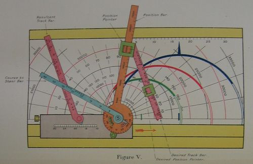
The Position Bar (shown in orange) was pivoted at point S and scaled along its length in thousands of yards. It would be swung to the proper angle to indicate the target's inclination (in attack mode) or the threat's relative bearing (in defence mode). A slider along the scale would be positioned to estimated range, and this bore a pivot point (referenced below). A disc about the hub at S would be referenced later, with the Course to Steer bar, and a small switch (shown in green) would indicate whether the attack from coming from port or starboard (as the instrument always depicts an attack from port).
The Desired Track Bar
The Desired Track Bar (shown in pink and pivoted from the position pointer on the position bar) depicted the proposed movement of the attacker to reach his preferred firing position. It pivoted from the position pointer and was graduated in "DISTANT TO RUN IN THOUSANDS OF YARDS" from the position pointer. A sliding Desired Position Pointer on this bar could be slid to a position to indicate the position the attacker would like to attain. The orientation of this bar and the placement of its pointer, then, would indicate a proposed firing position on the base plate relative to S.
The "Course to Steer" Bar
The "Course to Steer" Bar' (depicted in blue) pivoted around S and was graduated in knots on the same scale used on the target speed scale. A pointer near its hub indicated on the graduated disc at the base of the position bar. This would indicate the relative bearing the attacker would have to place the target to achieve the desired attack position indicated by the desired position pointer.
The Resultant Track Bar
The 'Resultant Track Bar (depicted in pink on the left) was on a pivot that was free to slide along the target's speed scale. It was graduated in "time in minutes to run 1,000 yards along the desired track bar."
"Type A" for Attack
- Main article: Renouf Torpedo Tactical Instrument Type A
This type, illustrated above, was the simplest. It was intended for use in cruisers, light cruisers, flotilla leaders, and destroyers. Its emphasis was delivering a torpedo attack.[8]
It could determine:[9]
- whether torpedo fire was possible from the present position
- when fire was possible, which torpedo setting would be most advantageous
- how to steer to attain a specific desired firing position
- how long it would take to attain that firing position
- the deflection setting for the torpedo deflection sight
In 1919, five were manufactured by Elliott Brothers for use in light cruisers and flotilla leaders, and a follow-on plan to further distribute to sixteen flotilla leaders, 48 light cruisers, four new vessels and 23 miscellaneous ships and bases.[10]
"Type B" for Battleships
- Main article: Renouf Torpedo Tactical Instrument Type B
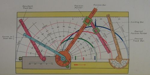
This type was intended for use aboard battleships and battlecruisers that were not flagships. The emphasis here was primarily defensive, but could also be used for attack calculations if torpedo circles of one's own torpedoes were substituted for those of the enemy. [12]
The Type B was nearly identical to the Type A, adding just one more bar called the "Avoiding Bar".[13]
The "B" augmented the functionality of the "A" by permitting these defensive problems to be illustrated:[14]
- are we within range of enemy torpedoes?
- if so, what course change is sufficient to cause them to fall short?
- what is the track angle of the enemy's torpedo, in case I want to comb the wakes?
- how long until his torpedo crosses my track?
In 1919, six were manufactured by Elliott Brothers, one for use at Vernon and the remainder in battleships and battle cruisers. A follow-on plan was also supplied to distribute forty-six devices, primarily to capital ships and large cruisers.[15]
"Type F" for Flagships
- Main article: Renouf Torpedo Tactical Instrument Type F
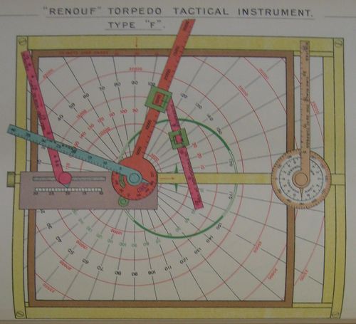
This was for use in flagships, and was the most complex model, as it was oriented toward torpedo attack and defence not at the ship level, but the level of a division, a squadron, or even three squadrons. It could also help identify, from the perspective of the fleet being considered, safe and unsafe arcs for one's own torpedo fire.
It was twice as large as Types A and B and required three sets of fittings to meet its diverse functions:[17]
- its "Course to Steer" fittings enabled the device to perform the functions of the Type B, and also to calculate when how long before an attacker could fire his torpedoes.
- its "Squadron" fittings were helpful when the attacker or target were not a single ship but a division, squadron, or three squadrons
- its "Own Torpedo" fittings allowed it to deal with hazards posed by friendly torpedoes
In 1919, nine were manufactured by Elliott Brothers, one for use at Vernon, one at Defiance and the remainder in battleships and battle cruisers. Unlike the simpler devices, no more than these nine would be manufactured,[18] though by 1920, the Staff College at Greenwich had taken one of those previously assigned to a ship, and the ships had been changed slightly.[19]
"Type M"
- Main article: Renouf Torpedo Tactical Instrument Type M
This model was first mentioned in the Annual Report of the Torpedo School, 1919. In that year, twenty-eight were to be eventually allocated, primarily to flag officers commanding capital ship formations. It seems possible that it was being evaluated as a possible replacement for the Type F.[20][Inference]
By 1921, only two had been issued, one each to Queen Elizabeth and Barham.[21]
History and Deployment
Drawings of capital ship torpedo control arrangements made in 1918 show that Eagle and Hood were to use Renouf instruments.[22]
It should be apparent that these instruments had some complexity, which made them somewhat confusing to learn and use correctly. Moreover, the general lessons of mechanical rigidity which had prompted a general trend toward simplifying the service's torpedo directors and sights were certainly an issue here: there are only so many dials and levers one can string together before the result is a wobbly mess.
In 1921, all types of Renouf instruments were under evaluation for ideas that would render them "less complicated and less liable to foul." One criticism was that the various bars fouled in various positions and the operator had to work with one grouping of circles at a time. It was thought desireable that perhaps the circles might be made such that they could be handled independently.[23]
While Annual Reports of the Torpedo School mentioned the various types of Renouf instruments with great regularity through 1922, in 1923 they are collectively covered by a simple note under the subject of Torpedo Defence: "Renouf Instruments have been found to be of little value, and it is probable that they will be withdrawn shortly." While I can find no affirmative order to abandon them, the absence of any mention of them through 1928 indicates strongly that their complexity, in the end, prompted the Royal Navy to focus on simpler devices such as the Torpedo Control Discs.[24]
See Also
- Renouf Torpedo Tactical Instrument Type A
- Renouf Torpedo Tactical Instrument Type B
- Renouf Torpedo Tactical Instrument Type F
- Renouf Torpedo Tactical Instrument Type M
Bibliography
- H.M.S. Vernon. Annual Report of the Torpedo School, 1917. Originally C.B. 1474. Copy 7 at The National Archives. ADM 189/37.
- H.M.S. Vernon. Annual Report of the Torpedo School, 1918. C.B. 1527. Copy 143 at The National Archives. ADM 189/38.
- H.M.S. Vernon. Annual Report of the Torpedo School, 1919. C.B. 1569. Copy 103 at The National Archives. ADM 189/39.
- Text Book on Renouf Torpedo Tactical Instruments, C.B. 890 – no known copies extant.[25]
Footnotes
- ↑ Annual Report of the Torpedo School, 1917. pp. 201-206, also Plates thereat.
- ↑ Annual Report of the Torpedo School, 1918. p. 181, Fig I..
- ↑ Annual Report of the Torpedo School, 1918. p. 182, Fig II.
- ↑ Annual Report of the Torpedo School, 1918. p. 182, Fig III.
- ↑ Annual Report of the Torpedo School, 1918. Plate 22.
- ↑ Link to material from Torpedo Control Handbook
- ↑ Annual Report of the Torpedo School, 1918. Plate 123.
- ↑ Annual Report of the Torpedo School, 1918. p. 180.
- ↑ Annual Report of the Torpedo School, 1918. p. 181.
- ↑ Annual Report of the Torpedo School, 1919. pp. 118, 119.
- ↑ Annual Report of the Torpedo School, 1918. Plate 125.
- ↑ Annual Report of the Torpedo School, 1918. p. 181.
- ↑ Annual Report of the Torpedo School, 1918. p. 185.
- ↑ Annual Report of the Torpedo School, 1918. p. 181.
- ↑ Annual Report of the Torpedo School, 1919. pp. 118, 119.
- ↑ Annual Report of the Torpedo School, 1918. Plate 127.
- ↑ Annual Report of the Torpedo School, 1918. p. 181.
- ↑ Annual Report of the Torpedo School, 1919. pp. 119, 120.
- ↑ Annual Report of the Torpedo School, 1920. p. 91.
- ↑ Annual Report of the Torpedo School, 1919. pp. 120-124.
- ↑ Annual Report of the Torpedo School, 1921. p. 144.
- ↑ Annual Report of the Torpedo School, 1918. Plates 132, 133.
- ↑ Annual Report of the Torpedo School, 1921. p. 144.
- ↑ Annual Report of the Torpedo School, 1923. p. 134.
- ↑ Annual Report of the Torpedo School, 1919. p. 119.
![Figure I[2]](/tfs/images/thumb/3/3c/ARTS1918Page181Fig1.jpg/120px-ARTS1918Page181Fig1.jpg)
![Figure II[3]](/tfs/images/thumb/3/31/ARTS1918Page182Fig2.jpg/120px-ARTS1918Page182Fig2.jpg)
![Figure III[4]](/tfs/images/thumb/9/90/ARTS1918Page182Fig3.jpg/120px-ARTS1918Page182Fig3.jpg)

